LiveFlow
The LiveFlow settings lets you further configure the LiveFlow data of the capture.
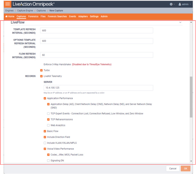
Template Refresh Interval
• Template Refresh Interval (Seconds): Enter or select the number of seconds in which LiveWire Virtual generates and sends IPFIX template records to LiveNX. The templates provide the instructions to LiveNX on how to interpret the template data records in the exported LiveFlow data. The default is set to 600 seconds (10 minutes). You can configure anywhere from 1 to 1800 seconds. If you make any changes to your template settings, it will take the specified number of seconds for the changes to take place.
NOTE: If you recently connected LiveWire Virtual to the network, it may take up to 600 seconds for LiveNX to see the LiveFlow data from LiveWire Virtual. You may want to adjust this setting to the desired intervals.
Options Template Refresh Interval
• Options Template Refresh Interval (Seconds): Enter or select the number of seconds in which LiveWire Virtual generates and sends IPFIX option template records to LiveNX. The templates provide the instructions to LiveNX on how to interpret the template data records in the exported LiveFlow data. The default is set to 600 seconds (10 minutes). You can configure anywhere from 1 to 1800 seconds. If you make any changes to your template settings, it will take the specified number of seconds for the changes to take place.
NOTE: If you recently connected LiveWire Virtual to the network, it may take up to 600 seconds for LiveNX to see the LiveFlow data from LiveWire Virtual. You may want to adjust this setting to the desired intervals.
Flow Refresh Interval
• Flow Refresh Interval (Seconds): Enter or select the number of seconds in which LiveWire Virtual generates and sends IPFIX data records to LiveNX. The default is set to 600 seconds (10 minutes). You can configure anywhere from 1 to 1800 seconds. If you make any changes to your template settings, it will take the specified number of seconds for the changes to take place.
• Enforce 3-way Handshake: Select this option to require a 3-way handshake (SYN, SYN-ACK, ACK) for a TCP flow in order for it to be included in processing and analyzing. If ThreatEye Telemetry is enabled below, then Enforce 3-way Handshake is automatically disabled.
• Turbo: Select this option to enable multi-stream CTD (also called Turbo mode) which is done in the capture template. This option will only be configurable (and enabled by default) for virtual capture engines with the Large or Unlimited LiveFlow activation feature.
Records
• LiveNX Telemetry: Select this option to send LiveFlow telemetry to a specific LiveNX server configured below.
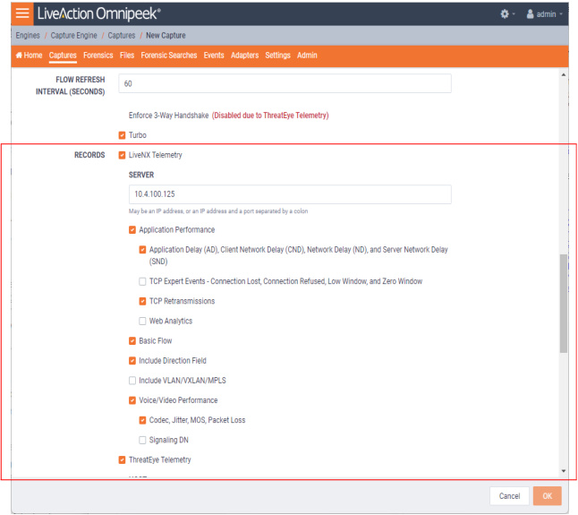
• Server: Displays the IP address of the LiveNX server receiving the LiveFlow data from LiveWire Virtual. To change the IP address, enter the IP address of the desired LiveNX server.
• Application Performance: Select this option to generate AVC IPFIX records.
• Application Delay (AD), Client Network Delay (CND), Network Delay (ND), and Server Network Delay (SND): Select this option to perform and report latency analysis when AVC IPFIX records are generated.
• TCP Expert Events -Connection Lost, Connection Refused, Low Window, and Zero Window: Select this option to perform TCP quality analysis (Expert) when AVC IPFIX records are generated.
• TCP Retransmissions: Select this option to perform TCP retransmission analysis (Expert) when AVC IPFIX records are generated.
• Web Analytics: Select this option to perform web analytics when AVC IPFIX records are generated.
• Decrypt Packets: Select this option to perform decryption on HTTPS packets when Web Analytics is enabled.
• Decrypt Packets: Select this option to perform decryption on HTTPS packets when Web Analytics is enabled.
• Basic Flow: Select this option to generate FNF IPFIX records.
• Include Direction Field: Select this option to send the ‘flowDirection’ key in unidirectional IPFIX records indicating the flow direction (0 for ingress, 1 for egress).
• Include VLAN/VXLAN/MPLS: Select this option to perform MPLS, VLAN, and VXLAN analysis when AVC, FNF, or MediaNet IPFIX records are generated.
• Voice/Video Performance: Select this option to generate MediaNet IPFIX records.
• Codec, Jitter, MOS, Packet Loss: Select this option perform RTP analysis when MediaNet IPFIX records are generated.
• Signaling DN: Select this option to generate Signaling DN IPFIX records when MediaNet IPFIX records are generated.
• ThreatEye Telemetry: Select this option to send LiveFlow telemetry to a specific ThreatEye host configured below.
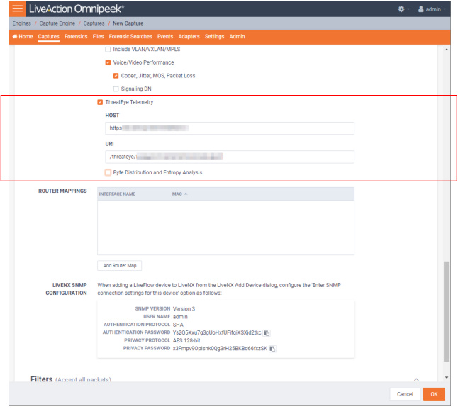
• Host: The Host (together with the URI) specifies the location of the ThreatEye analyzer and indicates where to send ThreatEye telemetry. The Host is provided by LiveAction and is made available as part of the licensing process. The Host must be configured if ThreatEye Telemetry is enabled.
• URI: The URI (together with the Host) specifies the location of the ThreatEye analyzer and indicates where to send ThreatEye telemetry. The URI is provided by LiveAction and is made available as part of the licensing process. The URI must be configured if ThreatEye Telemetry is enabled.
• Byte Distribution and Entropy Analysis: Select this option to enable the collection of byte distribution and entropy analysis metadata for Encrypted Traffic Analysis (ETA). This data is used to identify malware communications in encrypted traffic.
NOTE: You must enable a LiveNX Telemetry and/or ThreatEye Telemetry record type; otherwise, the button is disabled.
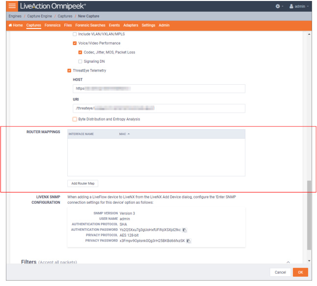
Router Mappings
• Router Mappings: Router mappings are used exclusively when you are exporting LiveFlow data to LiveNX, and are used by LiveNX to display aggregated traffic from different segments as separate interfaces per the router map entries you enter in the Router Mappings settings.
To add a router map entry for any adapter, you will need to specify an interface name (ifname) and a MAC address of the gateway or router separated by a forward slash (e.g., router_1/22:33:44:55:66:77). The interface name can be up to 15 characters, and can include letters, numbers, and underscores. This will tell LiveNX to display aggregated traffic from different segments as separate interfaces per the router map entries.
To find the MAC address of the gateway or router, the CLI can be used; otherwise, capture some traffic, or do a Forensics search and look at the Nodes view in hierarchical mode. The top level addresses should be the MAC addresses of the gateways and routers for each segment being captured.
NOTE: Although the CLI may display the MAC address using the abbreviated dot notation, the address must be formatted in full colon notation in the LiveWire Router Mapping entry dialog.
• Interface Name: Displays the interface name of the router. All interface names must be unique, must not be empty, must not be more than 15 characters long, and may only include the following characters: numbers, letters and an underscore (_).
• MAC: Displays the MAC address of the router. All MAC addresses must be unique and must be a valid MAC address.
• Add Router Map: Click to add a new router mapping. You can add an unlimited number of router mappings.
LiveNX SNMP Configuration
• LiveNX SNMP Configuration: For each LiveWire Virtual device that you want to use with LiveNX, you must use the Web client in LiveNX to add the device to LiveNX (see the LiveNX documentation). Since you are most likely adding LiveWire Virtual as an SNMP device to LiveNX, you will need the information provided below when adding the LiveWire Virtual device.
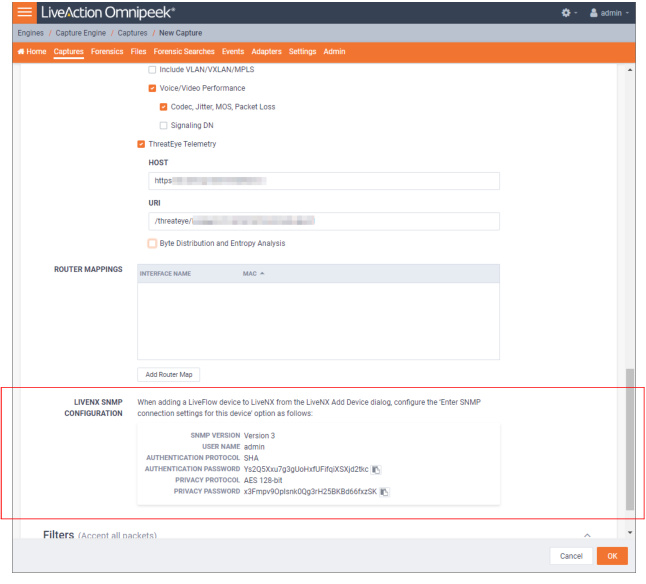
When configuring the 'Enter SNMP connection settings for this device' option from the Add Device dialog in LiveNX client, configure the option as follows:
SNMP Version: Version 3
User Name: admin
Authentication Protocol: SHA
Authentication Password: Ys2Q5Xxu7g3gUoHxfUFifqiXSXjd2tkc
Privacy Protocol: AES 128-bit
Privacy Password: x3Fmpv9OpIsnk0Qg3rH25BKBd66fxzSK
User Name: admin
Authentication Protocol: SHA
Authentication Password: Ys2Q5Xxu7g3gUoHxfUFifqiXSXjd2tkc
Privacy Protocol: AES 128-bit
Privacy Password: x3Fmpv9OpIsnk0Qg3rH25BKBd66fxzSK
NOTE: You can configure and change the Authentication Password and Privacy Password. See ‘SNMP Credentials’ in Configure.